FM4 SERIES GATE VALVES
The Valveworks USA FM4 Series consists of a lineup of gate valves with reliable, proven designs where a 7 1/16" bore is required. This series of gate valves offers the user several options depending on the specific application including achieving a positive seal at wellbore/ flowline pressures ranging from zero to 5,000 PSI.
FM4 Series gate valves are full bore, through conduit valves. This allows for downhole tools to be passed through the wellhead and/or Christmas tree and reduces turbulent flow. FM4 Series valves are similar to each other in design with only slight variations across the lineup, offering a high percentage of parts interchangeability, giving you an efficiency driven advantage in the management and maintenance of your gate valve fleet, and providing optimal life cycle management integrity.
This brochure provides an in-depth look at the details of this series of gate valves and explains the features, benefits, characteristics, dimensional & technical data, and other valuable information needed to determine which valve provides an optimal solution for your specific application.
PDF BrochureThe interactive tabbed chart below provides a detailed comparison of Valveworks USA FM4 Series Gate Valves, including Model FM4, Model FM4 SG, Model FM4 RC, Model FM4 RC SG, Model FM4 BSOP, and Model FM4 RC BSOP. These valves are designed for 7 1/16" bore wellhead and flowline operations up to 5,000 PSI. Visualizing models side-by-side helps users identify unidirectional vs. bidirectional configurations, cast vs. forged bodies, and expanding vs. slab gates.
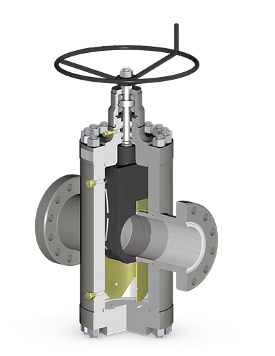
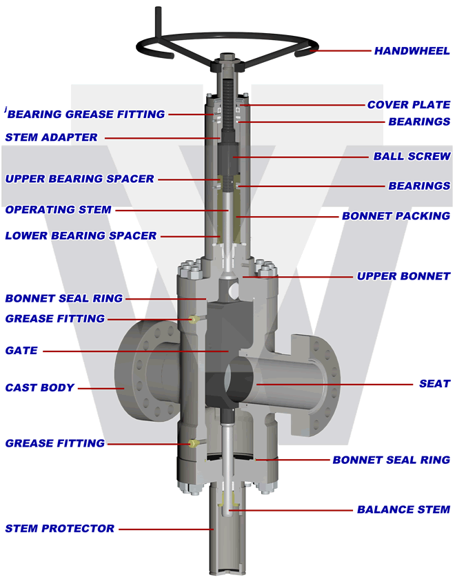
Unidirectional, Expanding Gate, Cast Body
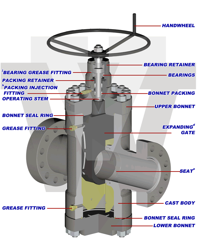
d) See engineering note titled "Expanding Gate Assembly Operation Explained".
h) Injectable packing can be energized into the valve bonnet stuffing box under pressure.
j) Valve bonnet / ball screw housing (where applicable) equipped with grease port(s) and fitting(s) for bearing lubrication.
Bidirectional, Slab Gate, Cast Body
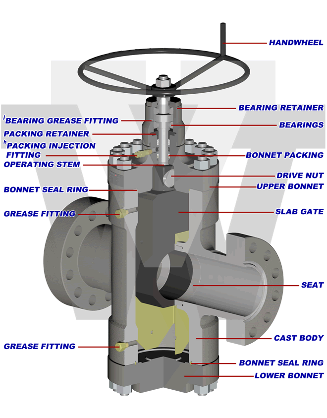
j) Valve bonnet / ball screw housing (where applicable) equipped with grease port(s) and fitting(s) for bearing lubrication.
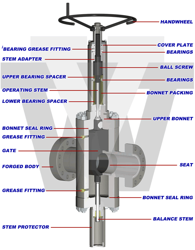
Unidirectional, Expanding Gate, Forged Body

d) See engineering note titled "Expanding Gate Assembly Operation Explained".
h) Injectable packing can be energized into the valve bonnet stuffing box under pressure.
j) Valve bonnet / ball screw housing (where applicable) equipped with grease port(s) and fitting(s) for bearing lubrication.
Bidirectional, Slab Gate, Forged Body
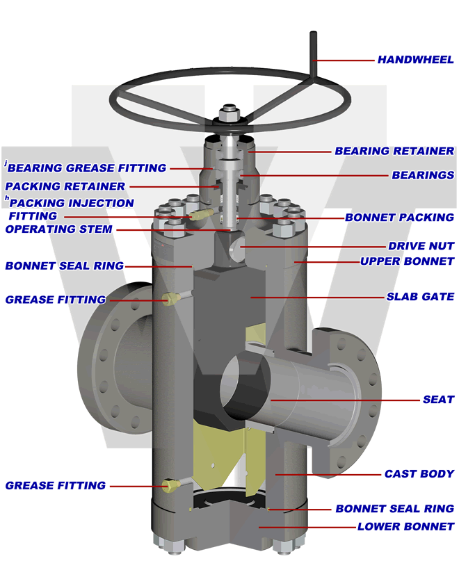
Bidirectional, Slab Gate, Cast Body
Bidirectional, Slab Gate, Forged Body
DISCLAIMER: THE ACTUAL PRODUCT MAY VARY SLIGHTLY FROM SHOWN SCHEMATIC DUE TO ENGINEERING APPROVED VARIATION.
WARNING: L7M / B7M STUDS CANNOT BE SUBSTITUED FOR L7 / B7 STUDS
PRODUCT FEATURES
This table provides a detailed comparison of Valveworks USA FM4 Series Gate Valves, including the FM4, FM4 SG, FM4 RC, FM4 RC SG, FM4 BSOP, and FM4 RC BSOP models. It outlines flow direction, bore sizes, pressure ratings, valve body types, gate configurations, sealing action, material classes, and other key specs for engineers and procurement teams to evaluate the best gate valve option for their applications.
| Key Features | FM4 | FM4 SG | FM4 RC | FM4 RC SG | FM4 BSOPf | FM4 RC BSOPf |
|---|---|---|---|---|---|---|
| Flow Direction | Unidirectionala | Bidirectional | Unidirectionala | Bidirectional | Bidirectional | Bidirectional |
| Available Bore Size & Pressure (PSI)b | 7 1/16" 2K, 3K, 5K | 7 1/16" 2K, 3K, 5K | 7 1/16" 2K, 3K, 5K | 7 1/16" 2K, 3K, 5K | 7 1/16" 3K, 5K | 7 1/16" 3K, 5K |
| Available PSLc | 1,2 | 1,2 | 1,2,3,3G,4 | 1,2,3,3G,4 | 1,2 | 1,2,3,3G,4 |
| Material Classes | AA,BB,CC,DD,EE,FF | AA,BB,CC,DD,EE,FF | AA,BB,CC,DD,EE,FF | AA,BB,CC,DD,EE,FF | AA,BB,CC,DD,EE,FF | AA,BB,CC,DD,EE,FF |
| Valve Body | Cast | Cast | Forged | Forged | Cast | Forged |
| Gate Type | Expandingd | Slab | Expandingd | Slab | Slab | Slab |
| Sealing Action | Mechanical | Pressure-Energized | Mechanical | Pressure-Energized | Pressure-Energized | Pressure-Energized |
| Operation | Manuale | Manuale | Manuale | Manuale | Manualf | Manualf |
| Bore Type | Thru-Conduitg | Thru-Conduitg | Thru-Conduitg | Thru-Conduitg | Thru-Conduitg | Thru-Conduitg |
| Gate/Seat Seal | Metal to Metal | Metal to Metal | Metal to Metal | Metal to Metal | Metal to Metal | Metal to Metal |
| Stem Type | Non-rising | Non-rising | Non-rising | Non-rising | Rising | Rising |
| Stem Packing | Opti-Seal | Opti-Seal | Opti-Seal | Opti-Seal | Opti-Seal | Opti-Seal |
| Repacking | Yesh | Yesh | Yesh | Yesh | Yesi | Yesi |
| Bearing | 2 | 2 | 2 | 2 | 3 | 3 |
| Body Lubrication Fittings | 2j | 2j | 2j | 2j | 2j | 2j |
| Body/Bonnet Connection | Bolted | Bolted | Bolted | Bolted | Bolted | Bolted |
| Balance Stem | No | No | No | No | Yes | Yes |
| End Connections | Flanged (RTJ) | Flanged (RTJ) | Flanged (RTJ) | Flanged (RTJ) | Flanged (RTJ) | Flanged (RTJ) |
| Temperature Range | -75°F to 250°F | -75°F to 250°F | -75°F to 250°F | -75°F to 250°F | -75°F to 250°F | -75°F to 250°F |
a. Equipped with a non-sealing seat on the upstream side. See engineering note titled “Model FM4 & Model FM4 RC” for details.
b. 7-1/16″ X 5-1/8″, 7-1/16″ X 6″, 7-1/16″ X 6-1/8″, 7-1/16″ X 6-3/8″, 7-1/16″ X 6-5/8″, and 7-1/16″ x 7-1/8″ available upon request.
c. Product Specification Level
d. See engineering note titled “Expanding Gate Assembly Operation Explained” for details.
e. Also referred to as “HANDWHEEL OPERATED”
f. Ball Screw Operated (BSOP) – Manual gate valve with torque/turn reduction operator (15-1/2 turns, full open/closed). See engineering note titled “Ball Screw Operated (BSOP)” for details.
g. Also referred to as “FULL OPENING”.
h. Injectable packing can be energized into the valve bonnet stuffing box under pressure.
i. Repacking is achieved via stem backseat method.
j. Valve bonnet/ball screw housing (where applicable) equipped with grease port(s) and fitting(s) for bearing lubrication
ENGINEERING NOTES
Expanding Gate Assembly Operation Explained – The expanding gate assembly consists of two main components; the gate (major) and the segment (minor). These components are assembled together using precision machined pins and high quality, precision formed and treated Nickel-Chromium alloy springs. When the valve is manually operated, the gate and segment act one against the other by means of a dual expanding wedge when the valve is either fully opened or fully closed. This expansion effect of the gate assembly against the valve seats, through parallel faces of the gate assembly, provides a strong and positive seal against pulsations and vibrations created by flow conditions.
Model FM4 and Model FM4 RC – These models are unidirectional gate valves equipped with an expanding gate assembly and a sealing seat in the downstream seat pocket. The upstream seat pocket is equipped with a non-sealing seat assembly. This allows pressure to bypass the upstream seat, equalize throughout the valve body, and only seal against the downstream seat assembly as the original Model M was intended. These models are marked with a flow direction arrow for accurate installation.
NOTE: When bidirectional operation is required, a slab gate valve is necessary. FM4 expanding gate valves (Model FM4 and Model FM4 RC) are not designed for bidirectional operation.
Pressure Testing – FM4 Series gate valves are not intended to be tested through the body lubrication fittings. These fittings are designed for lubrication purposes only. Shell tests and gate/seat tests shall be conducted from the end/outlet connection by qualified personnel.
Ball Screw Operated (BSOP) – FM4 Series gate valves are offered with an optional ball screw operator, which reduces the number of handwheel turns by approximately 60%, and greatly reduces the operating torque when opening and/or closing the valve. The number of turns required for a regular handwheel operated valve is between 39-1/4 to 39-1/2 from full open to full closed. The ball screw operated (BSOP) version of the same valve requires only 15-1/2 turns. This can be beneficial when time is of the essence.
TEMPERATURE RATING
The following table defines the temperature classifications for Valveworks USA gate valves, specifying the operating temperature ranges for each classification. These ratings ensure optimal performance in extreme cold and high-temperature industrial applications, making them ideal for oilfield and high-pressure environments.
| Temperature Classification | Operating Temperature Range (°F/°C) |
|---|---|
| K | -75°F (-60°C) to 180°F (82°C) |
| L | -50°F (-46°C) to 180°F (82°C) |
| N | -50°F (-46°C) to 140°F (60°C) |
| P | -20°F (-29°C) to 180°F (82°C) |
| S | 0°F (-18°C) to 140°F (60°C) |
| T | 0°F (-18°C) to 180°F (82°C) |
| U | 0°F (-18°C) to 250°F (121°C) |
| V | 35°F (2°C) to 250°F (121°C) |
TABLE 3 – MATERIAL REQUIREMENTS
The following table details the API 6A material class requirements for Valveworks USA gate valves, specifying the minimum material composition for body, bonnet, end connections, outlet connections, pressure-controlling parts, and stems. This classification ensures compliance with high-pressure industrial and oilfield standards.
| Material Class | Service Type | Minimum Material Requirements | |
|---|---|---|---|
| Body, Bonnet, End & Outlet Connections | Pressure-Controlling Parts & Stems | ||
| AA | General Service | Carbon or Low-Alloy Steel | Carbon or Low-Alloy Steel |
| BB | General Service | Carbon or Low-Alloy Steel | Stainless Steel |
| CC | General Service | Stainless Steel | Stainless Steel |
| DD | Sour Servicea | Carbon or Low-Alloy Steelb | Carbon or Low-Alloy Steelb |
| EE | Sour Servicea | Carbon or Low-Alloy Steelb | Stainless Steelb |
| FF | Sour Servicea | Stainless Steelb | Stainless Steelb |
| HH | Sour Servicea | Corrosion-Resistant Alloy (CRA)acd | Corrosion-Resistant Alloy (CRA)acd |
VALVEWORKS USA GATE VALVE MODEL EXPLANATION

FLANGED GATE VALVES
This table provides dimensional specifications for Valveworks USA FM4 Series Gate Valves with a 7 1/16" bore. It includes key data such as working pressure (PSI), face-to-face dimensions, bore centerline measurements, handwheel size, and approximate weight for different pressure classes (2K, 3K, 5K).
| Size | WP (PSI) | A | B | C | D | E | NT | RJ | BSS | N | WT (LBS) | HT (FT-LBS) |
|---|---|---|---|---|---|---|---|---|---|---|---|---|
| 7 1/16 | 2K | 25 1/8 | 7 1/16 | 16 5/8 | 33 1/2 | 24 | 39 1/4 | R-45 | 1 1/4 | 12 | 1047 | — |
| 7 1/16 | 3K | 28 1/8 | 7 1/16 | 16 5/8 | 33 1/2 | 24 | 39 1/4 | R-45 | 1 1/4 | 12 | 1550 | — |
| 7 1/16 | 5K | 32 | 7 1/16 | 16 5/8 | 33 1/2 | 30 | 39 1/4 | R-46 | 1 1/4 | 12 | 1650 | — |
BALL SCREW GATE VALVES
This table displays the dimensional data for Valveworks USA FM4 RC BSOP Series Gate Valves with a 7 1/16" bore size. It includes working pressures of 3K and 5K PSI, with key dimensions such as face-to-face length, bore centerline to top/bottom, handwheel diameter, number of turns, ring joint size, bonnet stud size, weight, and handwheel torque.
| Size | WP (PSI) | A | B | C | D | E | NT | RJ | BSS | N | WT (LBS) | HT (FT-LBS) |
|---|---|---|---|---|---|---|---|---|---|---|---|---|
| 7 1/16 | 3K | 28 1/8 | 7 1/16 | 30 1/8 | 56 | 28 | 15 1/2 | R-45 | 1 1/4 | 12 | 1915 | — |
| 7 1/16 | 5K | 32 | 7 1/16 | 30 1/8 | 56 | 28 | 15 1/2 | R-46 | 1 1/4 | 12 | 2015 | — |
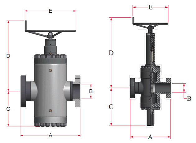
DIMENSION TABLE KEY
The following table defines key dimensional terms used in Valveworks USA gate valve specifications. Each key provides a description of its corresponding measurement or feature, ensuring clarity for engineers and professionals in high-pressure industrial applications.
| Key | Description |
|---|---|
| A | Face to Face |
| B | Valve Bore Size (Nominal) |
| C | Bore Centerline to Bottom |
| D | Bore Centerline to Top |
| E | Handwheel Diameter |
| NT | Number of Turns |
| RJ | Ring Joint |
| TS | Thread Size |
| BBS | Bonnet Stud Size |
| N | Number of Studs |
| WT | Approximate Weight |
| HT | Handwheel Operating Torque |
ABBREVIATION KEY
- MSG = Model M Slab Gate
- MDS = Model M Unidirectional
- MRC SG = Model M Round Cavity Slab Gate
- MRC DS = Model M Round Cavity Unidirectional
- HWO = Handwheel Operated (manual)
- EXP = Expanding
- SG = Slab Gate
- FE = Flanged End
- RTJ = Ring Type Joint
- PSL = Product Specification Level
- PR = Performance Requirement
- LP = Line Pipe
- STC = Casing Short Thead
- LC = Casing Long Thead
- EU = Tubing, Ecternal Upset
- CRA = Corrosion-resistant Alloy
- XYL = Xylan®
- HF = Hardfaced